Electrical shading loss according to module strings |
  
|
Electrical shading loss according to module strings |
|
Remember that in a string of modules, the current of the less irradiated cell drives the current in a string., Therefore when one cell is shaded, this has a high influence on the full string.
This is the base of the idea of the calculation "according to strings": on each table in the shading 3D construction, we define rectangles, each of them representing one full string of modules. When one of these rectangles is touched by a shadow, it is considered inactive (for the beam component).
This shaded string appears as yellow on the animations. The electrical loss on the beam component is calculated from the difference between the full "rectangles" area and the "linear" shadings (grey), i.e. the yellow parts.
The calculation "according to module strings" is the historical way of computing the electrical effects of partial shadings in PVsyst, the only way up to the launching of the version 6. Remember that it is an approximation, especially valid in the big regular systems (rows or shed arrangements, arrays of trackers) and under some conditions. It is not really applicable for disorderly shadows, like for example in building integration.
The real effect of partial shadings on the electrical production of the PV field is non-linear, and depends on the interconnections between the modules. The only way for accurately calculating it is the "ModuleLayout" tool.
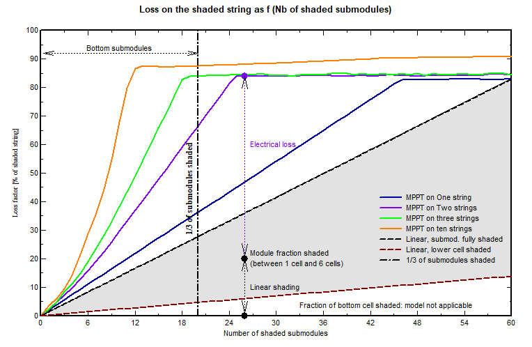
For understanding the issues of this approximation, a key point is to understand the following diagram, showing the real shading factor on a given string, as a function to the number of shaded sub-modules, as well as the number of strings in parallel on a same MPPT. This is fully explained in the page "Effect of the by-pass diodes".
Regular rows arrangements
In the case of regular sheds or tracker arrays, when the modules are in landscape, the bottom shed always affects all the bottom sub.modules, i.e. 1/3 of the submodules.
We can see here that when we have more than 2 strings in parallel (green curve), the loss (for beam) is complete. This justifies our hypothesis that when a part of the table is shaded the production is completely lost.
With one only string on each MPPT (blue line), the curve shows that when 1/3 of sub-modules are shaded, the loss factor is only around 35% (of the global). We should indeed define a "fraction for electrical effect" of the order of 42% (35% / 83% of beam). This is namely the case when you have one only module in width in each shed. You can also get this result by putting all the Bottom strings of a big installation on the same inverter input.
If the modules are in portrait, all the sub-modules are shaded at the same time, we are on the extremity of the curve, always fully shaded.
With twin half-cut cells modules in portrait, only half the current is lost when the bottom part is shaded, therefore the rectangle-string width should be the half-length of the module.
Fraction for electrical effect
At a given time, the basic global shading factor is calculated from the shaded areas (yellow + grey areas / total area of the tables), and the electrical contribution - applied to the beam - is related to the yellow area.
This diagram shows that when we are not on the plateau (i.e. depending on the number of shaded sub-modules), the loss may be lower. During the simulation, PVsyst proposes to weight the corresponding energy loss by a factor named "Fraction for electrical effect". This correction is obviously not correct for each hour individually, but allows to modulate the final energy loss for the whole year.
Therefore we can consider that the calculation of the electrical factor according to the rectangle's areas gives an upper limit of the real shading loss.
Other configurations
With disorderly shadows, the number of modules simultaneously shaded is unpredictable, and therefore this tool is not really applicable. Before the Module Layout availability, PVsyst advised to apply this Fraction for electrical effect to the shading factor calculated from the shaded areas, but did not give any way of estimating this factor.
The "Fraction for electrical effect" is dependent on the shades distribution on the field and the electrical array configuration. As stated above, for a shed arrangement (where the shades are very "regular"), it is near to 100%. When with more "distributed" shades like chimneys, far buildings, trees, it could probably be of the order of 60 to 80%, depending on the "regularity" of the shade (a diagonal-like shade has a lower impact as it concerns modules better distributed in the array).
Module Layout reference
Now the Module Layout tool provides an accurate way of computing the real electrical losses in any situation. This may help for the evaluation of the "Fraction for electrical effect".
However the use of this tool is complex: it requires to define the exact positioning of each module in the scene, and their attribution to a given inverter input. This is really feasible either with rather regular systems, or with little systems when the configuration is complex (building integration).
Extension to very big systems
But the Module Layout is only useable with systems of the order of some few MWp at most. Either because of the complexity of the PV modules definition if this is not regular, and due to the computing time during the simulation. PVsyst fixes a "reasonable" limit of around 1 MWp, and an upper limit (that you can modify in the advanced parameters) of 5 MWp.
For very big systems, we advise to define a representative sub-system (for example corresponding to one central inverter), execute the simulation and evaluate the Electrical shading loss with both tools: Module Layout and rectangle-strings. This will allow to evaluate the "Fraction for electrical effect" representative of your system (usually close to 100% for regular systems).
Then you can simulate your full system using the option "According to module-strings", applying this pre-evaluated factor. This calculation requires the same computing time as the linear shading.
Thin objects
The calculation "according to module strings" has a special feature, allowing to evaluate the shading effect of thin objects which only shade a part of one individual cell (like fences, HV lines above a PV array, etc).
This kind of evaluation is not possible with the "Module Layout" tool.
- In the global scene, when editing your shading fields, you have to define the option "Partition" for each table of the scene.
- If the scene has several fields, you have the option of extending this rectangle size definition to all other fields.
- In the General "Near shadings" dialog, when these definitions are complete, you can choose "Use in simulation > According to Module strings" and define the "Fraction for electrical effect".
- As for the linear shadings, you have the option of a fast calculation (i.e. from the interpolation in the shading factor table), or a Slow calculation, with the full calculation of the shading factor from the 3D scene at each step of the simulation (a little bit more accurate).