Partition in strings of modules |
  
|
Partition in strings of modules |
|
The partition in rectangle-strings for the Electrical calculation is done in the dialog of each field/table definition in the 3D scene.
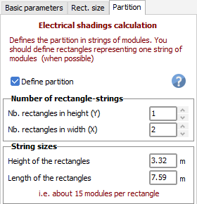
On each table in the 3D scene, you have to define rectangles, representing a full string of modules. You can define these rectangles either by their number in height and length of the table, or by their sizes. A rectangle should normally have the height of at least one module, either in length or in width, depending on the orientation (landscape or portrait).
The definition of full and regular rectangle-strings is not always possible, they are accepted even if the rectangle sizes don't match the field sizes, see below.
In the dialog (page "partition" of the 3D field editor), you have to specify whether you want to define a partition for this table, and the number of rectangles. The partition will appear as dotted lines on the Table.
Systems with "big" tables
In regular sheds or arrays of trackers, for minimizing the electrical losses you should ideally gather all the modules of a string in a same row within a table. Defining 2 rows (for example U-cabling) may produce a little bit more shading loss. The width of this "rectangle-string" will therefore be the width of the PV module in landscape, or its length in portrait.
For Twin half-cut cells modules, the ideal is to put them in portrait. In this case you can define a rectangle of half the length of the module. In landscape, such a module will behave exactly like a normal module: there is no benefit for the electrical shading loss.
NB: there is no way of defining Twin half-cut cells modules on several rows within the table: you have to use the ModuleLayout option.
It is not always possible to defined exactly one rectangle for one string. Some strings may have modules irregularly distributed on 2 rows. Remember that this electrical calculation is only an approximation. The particular cases should be calculated using the "ModuleLayout" tool.
Systems with "little" tables
Many systems are now defined by little tables (of less than about 10 modules), often imported from other CAD software, and often positioned on a hill, following the terrain.
In these cases the string partition is one rectangle in both sizes (i.e. 1 x 1). If the bottom and the top row of each table are connected to two different strings, you should split your table into 2 rectangles-strings.
Don't worry for the calculation: if your tables are positioned in rows, side-by-side on the terrain, defining one little part of the string in each table will be equivalent as defining a full string in a wide table. All the bottoms will be shaded at the same time, and the rest of the table will become inactive, in the same way as for a big table.
Defining rectangles as one module - Optimizers
Some people define each rectangle-strings as one only module. This is not the right way, except when you are using an optimizer on each module.
If the optimizer acts on 2 modules in series, you should define rectangle-strings representing 2 modules.
Extension to other tables
For implementing the Electrical calculation in the simulation, the partition has to be defined for each table of the scene.
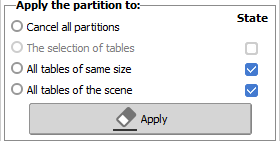
You can extend the definition of this table to the other tables of the scene.
| - Cancel all partitions | allows to suppress the definitions;.the electrical calculation is no more possible. |
| - The selection of tables | if you have defined a multiple selection in the global 3D scene, you can apply this partition to all selected tables. |
| - Alll tables of same size | the partition may be specific for a set of identical tables. |
| - All tables of the scene | defines all tables as "Partition defined" (even little tables 1 x 1), extends this choice when possible. |